Sand & Organic Filters
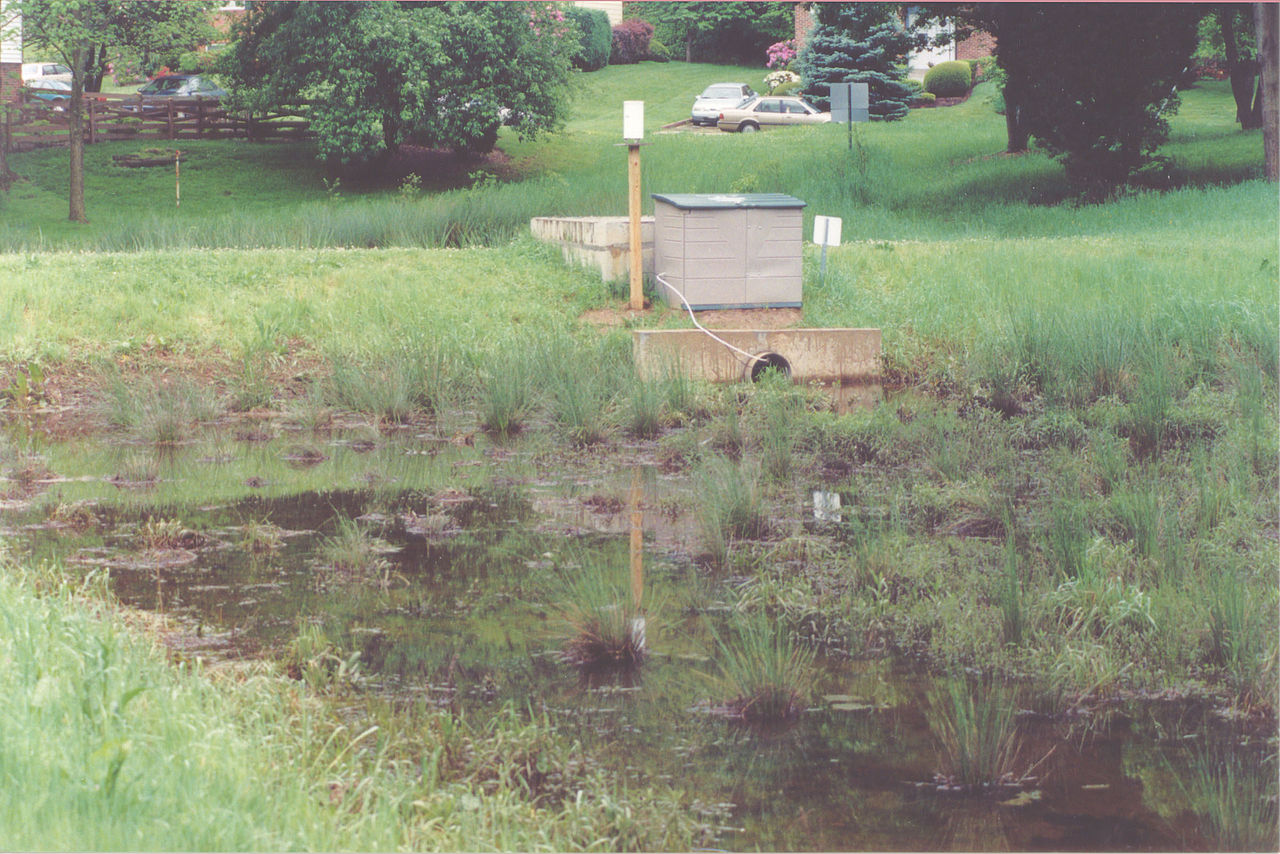
A peat-sand filter treating residential stormwater runoff
Description
Also known as filtration basins, sand and organic filters consist of self-contained beds of sand or peat (or combinations of these and other materials) either underlaid with perforated underdrains or designed with cells and baffles with inlets/outlets. Stormwater runoff is filtered through the sand, and in some designs may be subject to biological uptake. Runoff is discharged or conveyed to another BMP for further treatment. Another type of filter is the tree box filter. Information on this practice appears at the end of this section.
Ability to Meet Massachusetts Stormwater Management Standards
| Standard | Description |
| 2 - Peak Flow | Not applicable |
| 3 - Recharge | Not applicable |
| 4 - TSS Removal | 80% TSS removal credit provided it’s combined with one or more pretreatment BMPs prior to infiltration. |
| 5 - Higher Pollutant Loading | Can be used in lieu of an oil grit separator for certain land uses with higher potential pollutant loads of oil and grease such as high intensity parking lots and gas stations |
| 6 - Discharges near or to Critical Areas | Recommended treatment BMP. |
| 7 - Redevelopment | Suitable when combined with pretreatment BMP. Good option for ultra urban areas, since they consume no surface space. |
Advantages/Benefits
- Applicable to small drainage areas of 1 to 10 acres, although some designs may accept runoff of up to 50 acres.
- Good retrofit capability.
- Long design life if properly maintained.
- Good for densely populated urban areas and parking lots with high intensity use.
Disadvantages/Limitations
- Pretreatment required to prevent the filter media from clogging.
- Frequent maintenance required.
- Relatively costly to build and install.
- Without grass cover, the surface of sand filters can be extremely unattractive.
- May have odor problems, which can be overcome with design and maintenance.
- May not be able to be used on certain sites because of inadequate depth to bedrock or high groundwater.
- May not be effective in winter.
Pollutant Removal Efficiencies
- Total Suspended Solids (TSS): 80% with pretreatment
- Total Nitrogen: 20% to 40%
- Total Phosphorus: 10% to 50%
- Metals (copper, lead, zinc, cadmium): 50% to 90%
- Pathogens (coliform, e coli): Insufficient data
Special Features
Design as off-line device. Include a Sediment Forebay or equivalent pretreatment device.
LID Alternative
Bioretention areas
Maintenance
| Activity | Frequency |
| Inspect filters and remove debris | After every major storm for the first few months after construction is complete to ensure proper function and every 6 months thereafter. |
Sand Filters
Applicability
Sand filters are adaptable to most developments. They can be installed in areas with thin soils, high evaporation rates, low soil infiltration rates and limited space. Sand filters can be used in ultra-urban sites with small drainage areas that are completely impervious, such as small parking lots and fast food restaurants. They are suitable for many areas that are difficult to retrofit due to space limitations.
Sand filters can be used in areas with poor soil infiltration rates, where groundwater concerns restrict the use of infiltration, or for high pollutant loading areas. Design sand filters as off-line BMPs; they are intended primarily for quality control, not quantity control. A diversion structure, such as a flow splitter or weir, typically routes a portion of the runoff into the sand filter, while the remainder continues on to a stormwater quantity control BMP. Large sand filters can be designed to play a role in the control of peak discharge rates.
Because of the potential for clogging, install sand filters only at sites that have been stabilized. Never use sand filters as sedimentation traps during construction.
Effectiveness
Sand filters improve water quality by straining pollutants through a filtering media and by settling pollutants on top of the sand bed and/or in a pretreatment basin.
Planning Considerations
The surface of sand filters can be unattractive and create odors, and may not be appropriate for residential areas without a grass cover.
Sand filters require a sediment forebay or equivalent pretreatment device. Locate sand filters off-line from the primary conveyance/ detention systems. Design sand filters large enough to handle runoff from the storm associated with the required water quality volume, i.e., one inch or one half inch rain event.
Fit stormwater conveyances with flow splitters or weirs to route the required volume of runoff to the sand filter. Allow excess runoff to bypass the sand filter and continue on to another BMP designed to accommodate the necessary stormwater quantity.
Design
See the following for complete design references:
- Developments in Sand Filter Technology to Treat Stormwater Runoff, Article 105, and Further Developments in Sand Filter Technology, Article 106, in the Practice of Stormwater Protection
- Georgia Stormwater Manual 2004
- Connecticut Stormwater Manual
- North Carolina Department of Environment and
- Natural Resources Stormwater BMP Manual 2007
Two key design principles for sand filters are visibility and simplicity. A visible sand filter is more apt to be adequately operated and maintained. Complex designs are more expensive and difficult to operate and maintain. Typically, sand filter systems are designed with two components, a pretreatment component and a filtering component. The pretreatment component is a sediment forebay or vegetated filter strip designed to reduce the sediment load to the filtering component. Pre-settling also slows the runoff velocity and spreads it evenly across the top of the filter component.
Generally, the volume of the sediment forebay should be equal to or greater than the filtering capacity. Design the filter to capture finer silt and clay particles and other pollutants in the runoff. Sand filters are designed to function as a stormwater quality control practice, and not to provide detention for downstream areas. Therefore, locate them as off- line systems, away from the primary conveyance/ detention system. Design the pretreatment component to settle out coarse sediments that may clog the sand filter and reduce its effectiveness.
Use a design filtration rate of 2 inches/hour. Although this rate is low compared to published values for sand, it reflects actual rates achieved by sand filters in urban areas. Using Darcy’s Law, design the sand filter to completely drain within 24 hours or less, because there is little storm storage available in the sand filter if a second storm occurs.
Use eighteen inches of 0.02-inch to 0.04-inch diameter sand (smaller sand is acceptable) for the sand bed. Consider that sand may consolidate during construction. Stabilize the depth of the bed by wetting the sand periodically, allowing it to consolidate, and then adding extra sand. There are several possible sand bed configurations; most use a gravel bed at the bottom overlaid with a layer of sand and/or peat, leaf compost, or topsoil/grass. In all configurations, make sure the top surface layer of the bed is level to provide equal distribution of the runoff in the bed. The gravel bed layer is generally composed of 4 to 6 inches of 0.5-inch to 2-inch diameter gravel. Separate the gravel and top media layers with a layer of geotextile fabric to prevent sand from infiltrating into the gravel layer and the underdrain piping.
Recent research (Erickson, et al., 2007) shows that enhancing sand filters with steel wool can reduce phosphorus concentrations by as much as 80%.
Organic Media Filters
Organic media filters are essentially the same as sand filters with the sand media replaced or supplemented with another medium. Two examples are the peat sand filter and the compost sand filter. According to the Center for Watershed Protection, many practioners believe that organic sand filter systems have enhanced pollutant removal for many compounds due to the increased cation exchange capacity achieved by increasing the organic matter. See Performance of Delaware Sand Filter Assessed, Article 107 of the Practice of Watershed Protection.
Maintenance Features Incorporated in Filter Design Ease of access is essential for sand filter maintenance. Some designs use a geotextile layer, surface screen, or grating at the top to filter out coarse sediment and debris and for ease of maintenance. Typical maintenance for sand filters includes removing the top several inches of discolored sand and replacing it with clean media. Designs should include ramps, manhole steps, or ringbolts that allow a maintenance worker to manually remove this material. In addition, avoid heavy grates or manhole covers that cannot be lifted manually.
Trench Design
Trench designs have lateral underdrain pipes that are covered with 0.5-inch to 2-inch diameter gravel and geotextile fabric. The underdrains are underlaid with drainage matting, which is necessary to provide adequate hydraulic conductivity to the lateral pipes. Reinforce the underdrain piping so it withstands the weight of the overburden. The minimum grade of the piping should be 1/8 inch per foot (at 1% slope). An impermeable liner (clay, geomembrane, concrete) may be required under the filter to protect groundwater. If the impermeable liner is not required, install a geotextile liner, unless the bed has been excavated to bedrock. Make sure that the side slopes of the earthen embankments do not exceed 3:1 (horizontal: vertical). Fencing around sand filters may be needed to reduce safety hazards. Carefully selecting topsoil and sod for natural cover will help reduce the potential for failure. Sod with fine silts and clays will clog the top of the sand filter. Maximize the life of the sand filter by limiting its use to treating runoff from impervious areas only.
Construction
- Take care during construction to minimize the risk of premature failure of the sand filter.
- Diversion berms should be placed around the perimeter of the sand filters during all phases of construction.
- Sand filters should not be used as temporary sediment traps for construction activities.
- Consolidation of material in the sand filters during construction must be taken into consideration. The depth of the bed can be stabilized by wetting the sand periodically, allowing it to consolidate, and then adding extra sand.
- During and after excavation, all excavated materials should be placed downstream, away from the sand filters, to prevent redeposition during runoff events. All excavated materials should be handled properly and disposed of properly during and after construction.
Cold Weather Modifications
Surface sand filters will not provide treatment during the winter. Underground filers are not effective in winter unless the filter bed is placed below the frost line. Peat and compost media are ineffective during the winter in cold climates. These filters retain water and can freeze solid, and thus become impervious.
To prevent freezing, the diameter of the underdrain pipe should be at least 8 inches, and the slope of the underdrain pipe should be at least 1%. Place eighteen inches of gravel at the base of the filter. Make the slope of the inflow pipes at least 2%. In addition, place the filter below the frost line. If freezing cannot be prevented, remove snow from the contributing area and place it elsewhere.
Maintenance
Inspect sand filters after every major storm in the first few months after construction to ensure proper function. Thereafter, inspect the sand filter at least once every 6 months. Sand filters require frequent manual maintenance. Important maintenance tasks include raking the sand and removing surface sediment, trash and debris. Eventually a layer of sediment will accumulate on the top of the sand, which can be easily scraped off using rakes or other devices. Finer sediments will penetrate deeper into the sand over time, necessitating replacement of some (several inches) or all of the sand. Discolored sand indicates the presence of fine sediments. De- water and properly dispose of sand removed from the filter.
References
Erickson, Andrew J., et al., Enhanced Sand Filtration for Storm Water Phosphorus Removal, Journal of Environmental Engineering. Volume 133, Issue 5, pp. 485-497, May 2007.
Tree Box Filter
Description: The Tree Box Filter consists of an open bottom concrete barrel filled with a porous soil media, an underdrain in crushed gravel, and a tree. Stormwater is directed from surrounding impervious surfaces through the top of the soil media. Stormwater percolates through the media to the underlying ground. Treated stormwater beyond the design capacity is directed to the underdrain where it may be directed to a storm drain, other device, or surface water discharge.
Ability to Meet Massachusetts Stormwater Management Standards
| Standard | Description |
| 2 - Peak Flow | N/A |
| 3 - Recharge | No infiltration credit |
| 4 - TSS Removal | Presumed to remove 80% TSS |
| 5 - Higher Pollutant Loading | May be used as pretreatment device if lined |
| 6 - Discharges to near or to Critical Areas | Not suitable for vernal pools or swimming areas. At other critical areas, may be used as a pretreatment device. |
| 7 - Redevelopment | May be used for retrofit. |
Pollutant Removal Efficiencies
- Total Suspended Solids (TSS)-80% presumed for regulatory purposes
- Total phosphorus (TP) - Not Reported
- Dissolved Inorganic Nitrogen- Not Reported
- Zinc- Not Reported
- Pathogens (coliform, e. coli) - Not Reported
Advantages/Benefits
- May be used as a pretreatment device
- Provides decentralized stormwater treatment
- Ideal for redevelopment or in the ultra-urban setting
Disadvantages/Limitations
Special Features
Reduces volume and rate of runoff.
Maintenance
| Activity | Frequency |
| Check tree | Annually. Expected tree life is 5-10 years. |
| Rake media surface to maintain permeability | Twice a year |
| Replace media | When tree is replaced |