Waterway, Lined
Definition
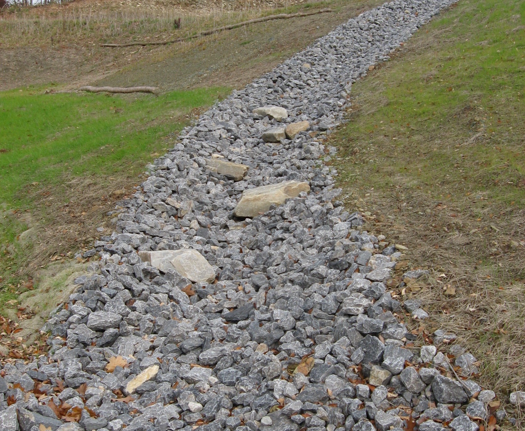
A waterway with an erosion resistant lining of concrete, stone, or other permanent material. The lined section extends up the side slopes to design flow depth. The earth above the permanent lining should be vegetated or otherwise protected.
Purpose
To provide for safe disposal of runoff from other conservation structures or from natural concentrations of flow, without damage by erosion or flooding, where unlined or grassed waterways would be inadequate.
Where Practice Applies
This practice applies where channel flow velocities exceed those acceptable for a grass lined waterway and/or conditions are unsuitable for the establishment of grass lined waterways. Specific conditions include:
- Concentrated runoff is of such magnitude that a lining is needed to control erosion.
- Steep grades, wetness, prolonged or continuous base flow, seepage, or piping would cause erosion.
- The location is such that use by people, animals, or vehicles preclude use of vegetated waterways.
- High value property or adjacent facilities warrant the extra cost to contain design runoff in limited space.
- Soils are highly erosive or other soil or climate conditions preclude using vegetation.
Planning Considerations
- Linings can consist of: rock riprap; cast-in-place concrete; flagstone mortared in place; or similar permanent linings.
- Riprap liners are considered flexible and are usually preferred to rigid liners.
- Riprap is less costly, adjusts to unstable foundation conditions, is less expensive to repair, and reduces outlet flow velocity.
- Riprap or paved channels can be constructed with grass lined slopes where site conditions warrant.
- Volume, velocity, and duration of flow expected are primary considerations for a lined waterway. Other factors include soil characteristics, safety, aesthetics, availability of land, compatibility with land use and surrounding environment, and maintenance requirements. The type of cross section that is selected depends on these factors.
- Typical cross sections that can be used include parabolic sections, and trapezoidal sections.
- Parabolic sections are suited for higher flows, but require the use of more land because the channels are generally shallow and wide. When velocities exceed the capability of vegetation, rock riprap can be used as a lining. When there is a continuous base flow in the channel it may be possible to use a combination of rock riprap and vegetation as a lining. The base flow would be carried by the riprap section and the higher flows by the vegetated section; as long as the vegetation is capable of withstanding the velocity.
- A trapezoidal channel is usually used where the flows are relatively large and at higher velocities. Trapezoidal channels usually take up less land than parabolic channels.
- Regardless of the channel shape selected, the outlet should be checked to determine if it is stable. It may be necessary to have some type of energy dissipater to prevent scour to the receiving outlet if there is an overflow or if velocities in the contributing channel are higher than the outlet can withstand.
- The Wetlands Protection Act requires that for any stream crossing or other work conducted in a wetland resource area, or within 100 feet of a wetland resource area, the proponent file a "Determination of Applicability" or a "Notice of Intent" with the local Conservation Commission.
Design Recommendations (Also see Riprap)
- Capacity: The minimum capacity should be adequate to carry the peak rate of runoff from a 10-year frequency storm.
- Cross Section: The cross section may be triangular, parabolic, or trapezoidal. Monolithic concrete may be rectangular.
Velocity
- Rock Riprap Lined Waterways: Rock riprap linings can be designed to withstand high velocities by choosing a stable rock size. Riprap should have a transition material (bedding) placed between the rock and the soil. This transition material can be either a well graded sand-gravel mixture or a geotextile fabric.
- Concrete-Lined Waterways: Velocity is usually not a limiting factor in the design of concrete-lined waterways. Keep in mind however that the flow velocity at the outlet must not exceed the allowable velocity for the receiving outlet.
- Drainage: Is not a factor when considering using a rock riprap waterway since subsurface water will drain through the transition material and the rock. Concrete lined channels may require drainage to reduce uplift pressure and collect seepage water.
- Filters or bedding: Filters or bedding should be used to prevent piping. Filter fabric may be used as the filter. Drains should be used, as required, to reduce uplift pressure and collect water. Weep holes may be used with drains if needed.
- Rock Riprap or Flagstone: Stone used for riprap or flagstone should be dense and hard enough to withstand exposure to air, water, freezing and thawing. Flagstone should be flat for ease of placement, and have the strength to resist exposure and breaking.
Construction Recommendations
- Outlet must be stable. Stabilize channel inlet points and install needed outlet protection during channel installation.
- Remove all trees, brush, stumps, and other objectionable material from channel and spoil areas and dispose of properly.
- Construct cross section to the lines and grades shown in plans. Install filter fabric or gravel layer as specified in the plan.
Common Trouble Points
- Foundation not excavated deep enough or wide enough: Riprap restricts channel flow, resulting in overflow and erosion.
- Side slopes too steep: Causes instability, stone movement and bank failure.
- Filter omitted or damaged during stone placement: Causes piping and bank instability.
- Riprap poorly graded or stones not placed to form a dense, stable channel lining: Results in stone displacement and erosion of foundation.
- Riprap not extended far enough downstream: Causes undercutting. Outlet must be stable.
- Riprap not blended to ground surface: Results in gullying along edge of riprap.
Maintenance
- Check riprap-lined waterways periodically and after every major storm for scouring below the riprap layer, and to see that the stones have not been dislodged by the flow. Plastic filter cloth, if used, should be completely covered and protected from sunlight.
- If the rocks have been displaced or undermined, the damaged areas should be repaired immediately. Woody vegetation should not be allowed to become established in the rock riprap and if present should be removed. Debris should not be allowed to accumulate in the channel.
- Give special attention to outlets and points where concentrated flow enters channel. Repair eroded areas promptly.
- Concrete-lined waterways should be checked to ensure that there is no undermining of the channel. If scour is occurring at the outlet, appropriate energy dissipation measures should be taken.
- If the waterway is below a high sediment-producing area, sediment should be trapped before it enters.
- Check for sediment accumulation, piping, bank instability, and scour holes. Sediment and debris deposits should be removed before they reduce the capacity of the channel.
References
Connecticut Council on Soil and Water Conservation, Connecticut Guidelines for Soil Erosion and Sediment Control, Hartford, CT, January, 1985.
Massachusetts Department of Environmental Protection, Office of Watershed Management, Nonpoint Source Program, Massachusetts Nonpoint Source Management Manual, Boston, Massachusetts, June, 1993.
Minnick, E. L., and H. T. Marshall, Stormwater Management and Erosion Control for Urban and Developing Areas in New Hampshire, Rockingham County Conservation District, August 1992.
North Carolina Department of Environment, Health, and Natural Resources, Erosion and Sediment Control Field Manual, Raleigh, NC, February 1991.