Subsurface Recharge Structures
Description
Subsurface structures are underground systems that capture runoff, and gradually infiltrate it into the groundwater through rock and gravel. There are a number of underground infiltration systems that can be installed o enhance groundwater recharge. The most common types include pre-cast concrete or plastic pits, chambers manufactured pipes), perforated pipes, and galleys.
Ability to Meet Massachusetts Stormwater Management Standards
| Standard | Description |
| 2 - Peak Flow | N/A |
| 3 - Recharge | Provides groundwater recharge |
| 4 - TSS Removal | 80% |
| 5 - Higher Pollutant Loading | May be used if 44% of TSS is removed with a pretreatment BMP prior to infiltration. Land uses with the potential to generate runoff with high concentrations of oil and grease require an oil grit separator or equivalent prior to discharge to the infiltration structure. Infiltration must be done in accordance with 314 CMR 5.00. |
| 6 - Discharges near or to Critical Areas | Highly recommended |
| 7 - Redevelopment | Suitable with pretreatment |
Advantages/Benefits
- Provides groundwater recharge
- Reduces downstream flooding
- Preserves the natural water balance of the site
- Can remove other pollutants besides TSS
- Can be installed on properties with limited space
- Useful in stormwater retrofit applications
Disadvantages/Limitations
- Limited data on field performance
- Susceptible to clogging by sediment
- Potential for mosquito breeding due to standing water if system fails
Pollutant Removal Efficiencies
- Total Suspended Solids (TSS) 80%
- Nutrients (Nitrogen, phosphorus) Insufficient data
- Metals (copper, lead, zinc, cadmium) Insufficient data
- Pathogens (coliform, e coli) Insufficient data
There are different types of subsurface structures
Infiltration Pit
A pre-cast concrete or plastic barrel with uniform perforations. The bottom of the pit should be closed with the lowest row of perforations at least 6 inches above the bottom, to serve as a sump. Infiltration pits typically include an observation well. The pits may be placed linearly, so that as the infiltrative surfaces in the first pit clog, the overflow moves to the second pit for exfiltration. Place an outlet near the top of the infiltration pit to accommodate emergency overflows. MassDEP provides recharge credit for storage below the emergency outflow invert. To make an infiltration pit, excavate the pit, wrap fabric around the barrel, place stone in the bottom of the pit, place the barrel in the pit, and then backfill stone around the barrel.
Take a boring or dig an observation trench at the site of each proposed pit.
Chambers
These are typically manufactured pipes containing open bottoms and sometimes perforations. The chambers are placed atop a stone bed. Take the same number of borings or observation pits as for infiltration trenches. Do not confuse these systems with underground detention systems (UDS) that use similar chambers. UDS are designed to attenuate peak rates of runoff--not to recharge groundwater.
Perforated Pipes
In this system, pipes containing perforations are placed in a leaching bed, similar to a Title 5 soil absorption system (SAS). The pipes dose the leaching bed. Take the same number of borings or observation pits as for infiltration trenches. Perforated pipes by themselves do not constitute a stormwater recharge system and receive no credit pursuant to Stormwater Standard No. 3. Do not confuse recharge systems that use perforated pipes with perforated pipes installed to lower the water table or divert groundwater flows.
Galleys
Similar to infiltration pits. Some designs consist of concrete perforated rectangular vaults. Others are modular systems usually placed under parking lots. When the galley design consists of a single rectangular perforated vault, conduct one boring or observation trench per galley. When the galleys consist of interlocking modular units, take the same number of borings or observation pits as for infiltration trenches. Do not confuse these galleys with vaults storing water for purposes of underground detention, which do not contain perforations.
Applicability
Subsurface structures are constructed to store stormwater temporarily and let it percolate into the underlying soil. These structures are used for small drainage areas (typically less than 2 acres). They are feasible only where the soil is adequately permeable and the maximum water table and/or bedrock elevation is sufficiently low. They can be used to control the quantity as well as quality of stormwater runoff, if properly designed and constructed. The structures serve as storage chambers for captured stormwater, while the soil matrix provides treatment.
Without adequate pretreatment, subsurface structures are not suitable for stormwater runoff from land uses or activities with the potential for high sediment or pollutant loads. Structural pretreatment BMPs for these systems include, but are not limited to, deep sump catch basins, proprietary separators, and oil/grit separators. They are suitable alternatives to traditional infiltration trenches and basins for space-limited sites. These systems can be installed beneath parking lots and other developed areas provided the systems can be accessed for routine maintenance.
Subsurface systems are highly prone to clogging. Pretreatment is always required unless the runoff is strictly from residential rooftops.
Effectiveness
Performance of subsurface systems varies by manufacturer and system design. Although there are limited field performance data, pollutant removal efficiency is expected to be similar to those of infiltration trenches and basins (i.e., up to 80% of TSS removal). MassDEP awards a TSS removal credit of 80% for systems designed in accordance with the specifications in this handbook.
Planning Considerations
Subsurface structures are excellent groundwater recharge alternatives where space is limited. Because infiltration systems discharge runoff to groundwater, they are inappropriate for use in areas with potentially higher pollutant loads (such as gas stations), unless adequate pretreatment is provided. In that event, oil grit separators, sand filters or equivalent BMPs must be used to remove sediment, floatables and grease prior to discharge to the subsurface structure.
Design
Unlike infiltration basins, widely accepted design standards and procedures for designing subsurface structures are not available. Generally, a subsurface structure is designed to store a ‘‘capture volume’’ of runoff for a specified period of ‘‘storage time.’’ The definition of capture volume differs depending on the purpose of the subsurface structure and the stormwater management program being used. Subsurface structures should infiltrate good quality runoff only. Pretreatment prior to infiltration is essential.
The composition, configuration and layout of subsurface structures varies considerably depending on the manufacturer. Follow the design criteria specified by vendors or system manufacturers.
Install subsurface structures in areas that are easily accessible for routine and non-routine maintenance.
As with infiltration trenches and basins, install subsurface structures only in soils having suitable infiltration capacities as determined through field testing. Determine the infiltrative capacity of the underlying native soil through the soil evaluation set forth in Volume 3. Never use a standard septic system percolation test to determine soil permeability because this test tends to greatly overestimate the infiltration capacity of soils.
Subsurface structures are typically designed to function off-line. Place a flow bypass structure upgradient of the infiltration structure to convey high flows around the structure during large storms.
Design the subsurface structure so that it drains within 72 hours after the storm event and completely dewaters between storms. Use a minimum draining time of 6 hours to ensure adequate pollutant removal. Design all ports to be mosquito-proof, i.e., to inhibit or reduce the number of mosquitoes able to breed within the BMP.
The minimum acceptable field infiltration rate is 0.17 inches per hour. Subsurface structures must be sized in accordance with the procedures set forth in Volume 3. Manufactured structures must also be sized in accordance with the manufacturers’ specifications. Design the system to totally exfiltrate within 72 hours.
Design the subsurface structure for live and dead loads appropriate for their location. Provide measures to dissipate inlet flow velocities and prevent channeling of the stone media. Generally, design the system so that inflow velocities are less than 2 feet per second (fps).
All of these devices must have an appropriate number of observation wells, to monitor the water surface elevation within the well, and to serve as a sampling port.
Each of these different types of structures, with the exception of perforated pipes in leaching fields similar to Title 5 systems, must have entry ports to allow worker access for maintenance, in accordance with OSHA requirements.
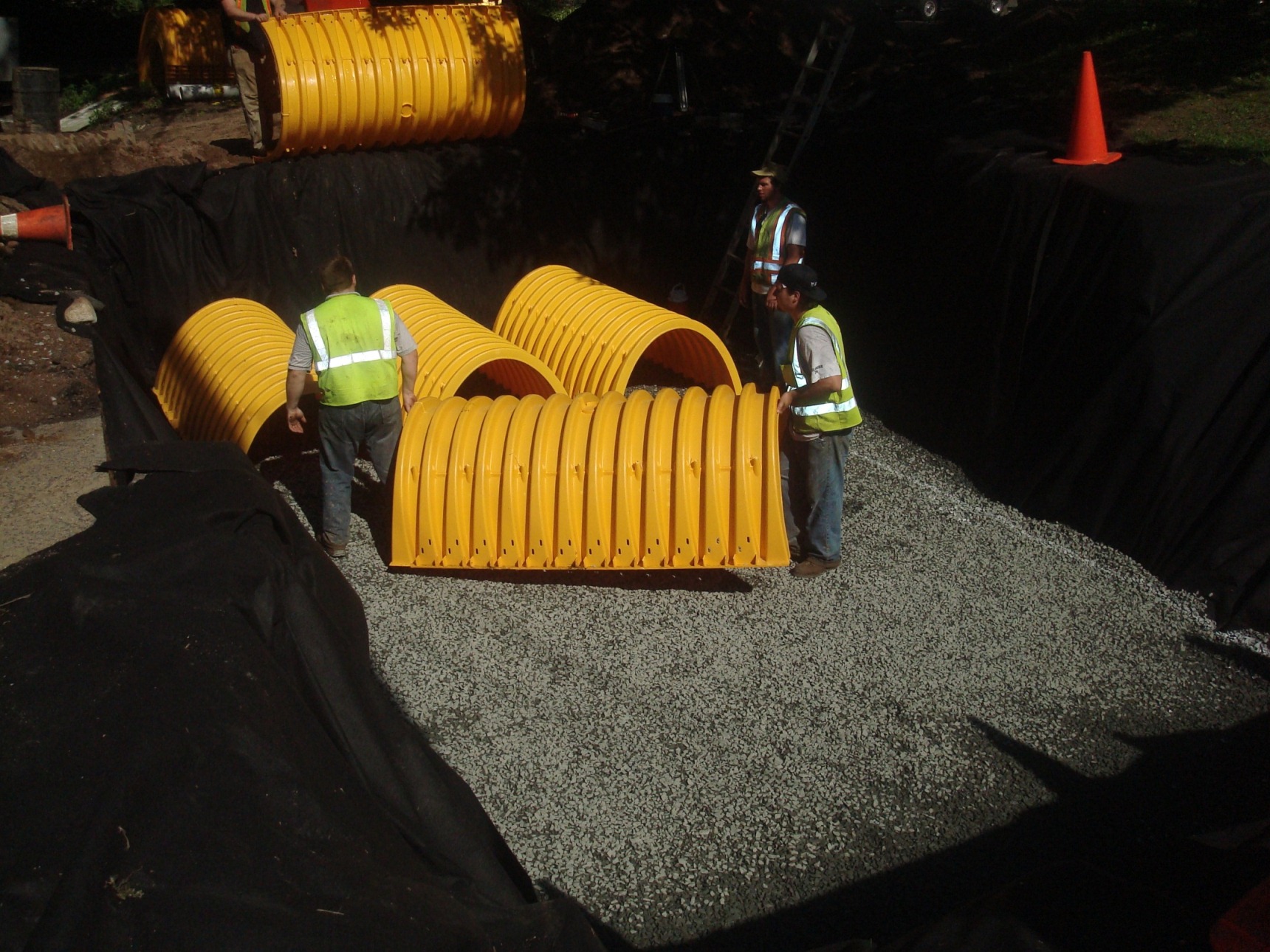
Construction
Stabilize the site prior to installing the subsurface structure. Do not allow runoff from any disturbed areas on the site to flow to the structure. Rope off the area where the subsurface structures are to be placed. Accomplish any required excavation with equipment placed just outside of this area. If the size of the area intended for exfiltration is too large to accommodate this approach, use trucks with low- pressure tires to minimize compaction. Do not allow any other vehicles within the area to be excavated. Keep the area above and immediately surrounding the subsurface structure roped off to all construction vehicles until the final top surface is installed (either paving or landscaping). This prevents additional compaction. When installing the final top surface, work from the edges to minimize compaction of the underlying soils.
Before installing the top surface, implement erosion and sediment controls to prevent sheet flow or wind blown sediment from entering the leach field. This includes, but is not limited to, minimizing land disturbances at any one time, placing stockpiles away from the area intended for infiltration, stabilizing any stockpiles through use of vegetation or tarps, and placing sediment fences around the perimeter of the infiltration field.
Provide an access port, man-way, and observation well to enable inspection of water levels within the system. Make the observation well pipe visible at grade (i.e., not buried).
Maintenance
Because subsurface structures are installed underground, they are extremely difficult to maintain. Inspect inlets at least twice a year. Remove any debris that might clog the system. Include mosquito controls in the Operation and Maintenance Plan.
Adapted from
Connecticut Department of Environmental Conservation. Connecticut Stormwater Quality Manual. 2004.
MassHighway. Storm Water Handbook for Highways and Bridges. May 2004.