Sediment Fence
Definition
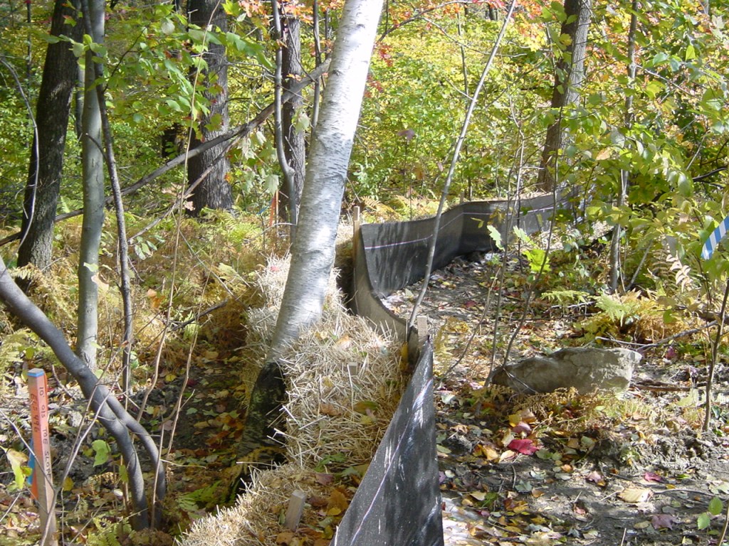
A temporary sediment barrier consisting of a filter fabric stretched across and attached to support- ing posts and entrenched. The sediment fence is constructed of stakes and synthetic filter fabric with a rigid wire fence backing where necessary for support. Sediment fence can be purchased with pockets pre-sewn to accept use of steel fence posts.
Purpose
- A sediment fence intercepts and detains small amounts of sediment from disturbed areas during construction operations and reduces runoff velocity down a slope.
- Sediment fences may also be used to catch wind-blown sand and to create an anchor for sand dune creation.
Where Practice Applies
- Below small disturbed areas of less than 1/4 acre per 100 feet of fence, where runoff may occur in the form of sheet and rill erosion.
- Where there is no concentration of water in a channel or other drainageway above the fence, and drainage area is usually not more than 1-1/2 acres.
- Where runoff can be stored behind the sediment fence without damaging the fence, or the submerged area behind the fence.
- Where erosion would occur only in the form of sheet erosion.
- Do not install sediment fences across streams, ditches, or waterways.
Advantages
- Removes sediments and prevents downstream damage from sediment deposits.
- Reduces the speed of runoff flow.
- Minimal clearing and grubbing required for installation.
- Sediment fences trap a much higher percentage of suspended sediments than straw bales.
Disadvantages/Problems
- Sediment fences are not practical where large flows of water are involved. Their use is recommended only for small drainage areas, and flow rates of less than 0.5 cfs.
- Flow should not be concentrated; it should be spread out over many linear feet of sediment fence.
- Problems may arise from incorrect selection of filter fabric or from improper installation.
- Sediment fences are not an adequate method of runoff control for anything deeper than sheet or overland flow.
Planning Considerations
- Sediment fences should be located where they will trap sediment; that is, where there will be contributing runoff. A sediment fence, located along the top of a ridge serves no useful purpose, except as it may be used to mark limits of a construction area. A sediment fence located at the upper end of a drainage area performs no sediment-collecting function.
- Sediment fences are preferable to straw barriers in many cases. While the failure rate is lower than that of straw barriers there are, however, many cases in which sediment fences have been improperly installed.
- Sediment fences have a low permeability to enhance sediment trapping. This will create ponding behind the fence, so they should not be located where ponding will cause property damage or a safety hazard.
- The sedimentation pool behind the fence is very effective and may reduce the need for sediment basins and traps.
- Sediment fences may be designed to store all the runoff from the design storm or located to allow bypass flow when the temporary sediment pool reaches a re-determined level.
- The drainage area must be restricted and the fence located so that water depth does not exceed 1.5 feet at any point.
- The expected life of a sediment fence is generally six months.
- To use sediment fences effectively, provide access to the locations where sediment accumulates and provide reinforced, stabilized outlets for emergency overflow.
- Sediment fence is most effective when used in conjunction with other practices such as perimeter dikes or diversions.
- Allow for safe bypass of storm flow to prevent overtopping failure of fence.
- Do not install sediment fence across intermittent or permanent streams, channels, or any location where concentrated flow is anticipated.
Design Recommendations
Depth of impounded water should not exceed 1.5 feet at any point along the fence.
Drainage area Limited to 1/4 acre per 100 ft of fence, and no more than 1.5 acres in total; or in combination with a sediment basin on a larger site. Area is further restricted by slope steepness as shown in the following table.
Maximum Slope
| Land Slope (%) | Distance Above Fence (feet) |
| 2 | 250 |
| 5 | 180 |
| 10 | 100 |
| 20 | 50 |
| 30 | 30 |
Location
- Locate the fence at least 10 feet from the toe of steep slopes to provide sediment storage and access for cleanout.
- The fence line should be nearly level through most of its length to impound a broad, temporary pool. The last 10 to 20 feet at each end of the fence should be swung slightly uphill (approximately 0.5 feet in elevation)to provide storage capacity.
- Stabilized outlets are required for bypass flow, unless the fence is designed to retain all runoff from the 10-year storm.
- The fence line may run slightly off level (grade less than 1%)if it terminates in a level section with a stabilized outlet, diversion, basin, or sediment trap. There must be no gullying along the fence or at the ends. A sediment fence should not be used as a diversion.
Materials and Use
Filter Fabric
The filter fabric used in a sediment fence must have sufficient strength to with- stand various stress conditions. It also must have the ability to allow passage of water while retaining soil particles. Filter fabric for a sediment fence is available commercially.
Support Posts
Four-inch diameter pine,1.33 lb./linear ft. steel, or sound quality hardwood with a minimum cross sectional area of 3.0 square inches. Steel posts should have projections for fastening fabric. Drive posts securely, at least 16 inches into the ground, on the downslope side of the trench. Space posts a maximum of 8 feet if fence is supported by wire, 6 feet if extra-strength fabric is used without support wire. Adjust spacing to place posts at low points along the fenceline.
Support wire
Wire fence (14 gauge with 6-inch mesh) is required to support standard- strength fabric.
Reinforced, stabilized outlets
- Any outlet where storm flow bypass occurs must be stabilized against erosion.
- Set outlet elevation so that water depth cannot exceed 1.5 feet at the lowest point along the fenceline.
- Set fabric height at 1 foot maximum between support posts spaced no more than 4 feet apart. Install a horizontal brace between the support posts to serve as an overflow weir and to support top of fabric. Provide a riprap splash pad a minimum 5 feet wide,1 foot deep, and 5 feet long on level grade. The finished surface of the riprap should blend with surrounding area, allowing no overfall. The area around the pad must be stable.
Construction Recommendations
- Dig a trench approximately 8 inches deep and 4 inches wide, or a V- trench; along the line of the fence, upslope side.
- Fasten support wire fence securely to the upslope side of fence posts with wire ties or staples. Wire should extend 6 inches into the trench.
- Attach continuous length of fabric to upslope side of fence posts. Avoid joints, particularly at low points in the fence line. Where joints are necessary, fasten fabric securely to support posts and overlap to the next post.
- Place the bottom one foot of fabric in the trench. Backfill with compacted earth or gravel.
- Filter cloth shall be fastened securely to the woven wire fence with ties spaced every 24 inches at the top, mid-section, and bottom.
- To reduce maintenance, a shallow sediment storage area may be excavated on the upslope side of fence where sedimentation is expected.
- Provide good access to deposition areas for cleanout and maintenance.
- Sediment fences should be removed when they have served their useful purpose, but not before the upslope area has been permanently stabilized. Retained sediment must be removed and properly disposed of, or mulched and seeded.
Common Trouble Points
Fence Sags or Collapses
- Drainage area too large,
- Too much sediment accumulation allowed before cleanout,
- Approach too steep, or
- Fence not adequately supported.
Fence fails from undercutting
- Bottom of fence not buried at least 8 inches at all points,
- Trench not backfilled with compacted earth or gravel,
- Fence installed on excessive slope, or
- Fence located across drainage way.
Fence is overtopped
- Storage capacity inadequate, or
- No provision made for safe bypass of storm flow, or
- Fence located across drainage way.
Erosion occurs around end of fence
- Fence terminates at elevation below the top of the temporary pool,
- Fence terminates at unstabilized area, or
- Fence located on excessive slope.
Maintenance
- Silt fences should be inspected routinely to determine if they require maintenance because they are full or have been damaged by construction equipment.
- Inspect silt fences immediately after each rainfall and at least daily during prolonged rainfall. Repair as necessary.
- Remove sediment deposits from behind the fence when they reach half the height of the fence or install a second fence. There are several challenges associated with cleaning out silt fences. Once the fabric is clogged with sediment, it can no longer drain slowly and function as originally designed. The result is typically a low volume sediment basin because the cleaning process (e.g., removal with a backhoe or similar equipment) doesn’t unclog the fabric. An alternative to removing the sediment is to leave it in place and install a new silt fence either above or below it to collect additional sediment. The best maintenance approach may be site-specific (e.g., small construction sites might not have sufficient space for an additional row of silt fence).
- Take care to avoid undermining the fence during cleanout. If the fabric tears, decomposes, or in any way becomes ineffective, replace it immediately.
- Remove all fencing materials after the contributing drainage area has been properly stabilized. Sediment deposits remaining after the fabric has been removed should be graded to conform with the existing topography and vegetated.
- Maintain an adequate access area around the silt fence so that inspections and maintenance can be performed.
References
Massachusetts Department of Environmental Protection, Office of Watershed Management, Nonpoint Source Program, Massachusetts Nonpoint Source Management Manual, Boston, Massachusetts, June,1993.
Minnick, E.L., and H.T. Marshall, Stormwater Management and Erosion Control for Urban and Developing Areas in New Hampshire, Rockingham County Conservation District, August 1992.
North Carolina Department of Environment, Health, and Natural Resources, Erosion and Sediment Control Field Manual, Raleigh, NC, February 1991.
"Proper Silt Fence Performance," Erosion Control, The Journal For Erosion & Sediment Control Professionals, Vol.1, No.3, July/August 1994.
U.S. Environmental Protection Agency, Storm Water Management For Construction Activities EPA-832-R-92-005, Washington, DC, September,1992.
Washington State Department of Ecology, Stormwater Management Manual for the Puget Sound Basin, Olympia, WA, February,1992.
U.S. Environmental Protection Agency, Stormwater Best Management Practice, Silt Fences, EPA 833-F-11-008, April 2012.
http://nepis.epa.gov/Exe/ZyPDF.cgi/P100EKRL.PDF?Dockey=P100EKRL.PDF