Leaching Catch Basin/Leaching Basin
Description
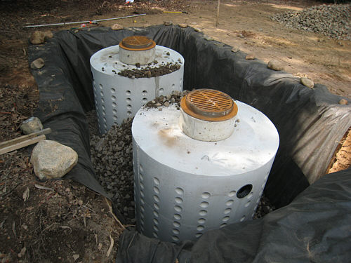
A leaching catch basin is a catch basin that is fabricated of barrel and riser sections that permit the infiltration of runoff into the ground. A leaching basin is a similar device, installed adjacent to a deep sump catch basin that provides pretreatment (see illustration). Because of this pretreatment, the
catch basin/leaching basin combination is preferable to the leaching catch basin, where feasible.
Leaching catch basins and leaching basins
should only be used in areas with highly permeable soils. Designers should also provide for the safe overflow of these devices in severe storm events, or in the event of clogging of the soils surrounding the device.
Leaching basins are generally set in an excavation lined with a geotextile. The basin is placed on a pad of free draining crushed stone, with the excavation around the basin back-filled with similar material. The base and barrel of the basin are perforated, so that water entering the basin can enter the surrounding stone fill and infiltrate into the ground. Leaching catch basins should be used as "off-line" devices (that is, they should not generally be piped in series as "flow-through" devices).
|
GENERAL INFORMATION
|
|
|
Applicable DEP Stormwater Management Policy Performance Standards
|
- Standards #3, #4:
- Standard #2 (peak rate control), if sufficient number of leaching catch basins are provided to handle the 10-year frequency storm.
|
|
TSS Removal
|
DEP Credit:
|
80%
|
|
|
Estimated Range from Literature:
|
>90%
|
|
Relative Cost
|
Construction: Low to moderate (depends on number of catch basins per acre
Maintenance: Moderate (annual cleaning required)
|
|
Potential Constraints to Use
|
- Depth to bedrock or other impermeable substratum
- Depth to groundwater
- Soils must be well-drained to permit infiltration
- Leaching catch basins should only be used where the water discharged will not compromise the integrity of the road base
|
|
Other Considerations
|
- Requires regular maintenance
- Not recommended where sediment loading is likely to result in clogging of infiltration surface
- Leaching catch basins do not provide pretreatment of runoff. A deep sump catch basin does provide for pretreatment prior to discharge to a leaching basin unit
|
|
Maintenance Requirements
|
- Inspection (typically annually, or more frequently as indicated by structure performance)
- Periodic sediment and debris removal (typically annually)
- Rehabilitation in the event of failure due to clogging
|
|
Primary Design Reference
|
MA DEP Technical Bulletin, (pending)
MassHighway Design Manual,
MassHighway Construction and Traffic Standard Details (Metric Edition, 1996).
|
|
DESIGN CRITERIA
|
|
|
Design Parameter
|
Criteria
|
|
Contributing Drainage Area
|
Less than 0.4 ha (1.0 acre).
For roadways, the tributary area for each catch basin will be much less than this, based on typical spacing of basins along a roadway.
|
|
Storm frequency for design flow
|
Varies with system.
To comply with Standard #3, recharge systems are sized for recharging an annual volume, not an event storm.
To comply with Standard #2 (peak rate control), size must be determined based on hydraulic/hydrologic modeling.
|
|
Annual Recharge Volume
|
Compute “annual recharge loss” using methodology specified in DEP Technical Bulletin (see Primary Design References),
|
|
Required Storage Volume
|
Compute storage volume required to compensate for “annual recharge loss” using methodology specified in DEP Technical Bulletin or use an alternative method conforming to accepted engineering practice. For peak rate control, compute required storage by accepted runoff estimation/routing practice for required design storm.
|
|
Stone Void Space
|
When the void space in crushed stone is used for storage, the specified stone should be uniformly sized. A porosity (volume of voids divided by total volume of bed) of 0.39 or less should be used for design.
|
|
Geotextile
|
The stone material surrounding the basin must be encapsulated by a geotextile fabric designed to prevent the migration of fine soil particles into the void spaces in the stone. Geotextile materials shall meet applicable MassHighway standard specifications, and must be selected based on an analysis of on-site soils conditions.
|
|
Depth to Bedrock or Impermeable Stratum
|
Minimum 0.6 meters (2 feet) below bottom of system.
|
Depth to Seasonal High Groundwater
|
Minimum 0.6 meters (2 feet) below bottom of system, unless engineering analysis demonstrates that lesser separation is feasible.
|
|
Structural design loading
|
Structural components should be designed for dead and live loads appropriate to their location. The minimum design load shall be H-20 loading.
|
|
Inlet grate
|
Design and placement of inlet grates may require consideration of the capacity of grates to pass design flows. Refer to MassHighway Drainage Manual for design of catch basin inlet capacity.
|
|
Provision for Overflow
|
Design and placement of leaching catch basins should consider the impact of runoff that exceeds the capacity of the device, either because of the magnitude of the event, or the clogging of the infiltration surface. Provisions for overflow might include redundant devices, paved “chutes” to discharge excess runoff to an acceptable outlet, or other measure.
|
|
Setbacks
|
Refer to Design Criteria for Recharge Wells and Galleys for recommended setbacks from surface water supplies, wells, foundations, septic systems, and steep slopes.
|
|
Other
|
Leaching catch basins are most effective as “beginning of system” or “off-line” devices (no inlet pipes)
|