Extended Detention Basin
Description
An extended detention basin provides a storage volume above the invert of the lowest outlet, to temporarily detain a portion of storm water runoff for an extended time period (up to 24 hours after a storm). By draining this volume over a period of about 24 hours, the basin provides pollutant removal by allowing time for settling of particulate fractions.
Extended detention can be combined with conventional detention for control of peak rates, as well as the extended draw-down of the water quality volume. An extended detention component can be incorporated into the design of a wet pond or created storm water wetlands, to provide enhancement of the treatment function of those BMPs.
Dry extended detention ponds have a greater risk of sediment re-suspension than do extended detention wet ponds, or extended detention wetlands, and generally do not provide as effective soluble pollutant removal. Extended detention may be designed as an on-line or off-line system.
|
GENERAL INFORMATION
|
|
Applicable DEP Stormwater Management Policy Performance Standards
|
Standards #2, #4
In some cases, dry extended detention basins can incorporate recharge functions to meet Standard #3.
|
|
TSS Removal
|
DEP Credit:
|
70%
|
|
|
Estimated Range from Literature:
|
60 - 80%
|
|
Relative Cost
|
Construction: Moderate
Maintenance: Moderate
|
|
Potential Constraints to Use
|
- Depth to groundwater (although groundwater levels may be controlled by design of outlet and design of embankment treatment)
- Depth to bedrock (excavation cost)
|
|
Other Considerations
|
- Can also be designed to control peak rates
- Design for extended draw-down and for control of high frequency storms can help reduce bank/channel erosion
- May increase water temperature, which may be of concern for watersheds with cold-water fisheries
- Sediment and debris may accumulate quickly
|
|
Maintenance Requirements
|
- Periodic mowing of embankments
- Removal of woody vegetation from embankments
- Removal of debris from outlet structures
- Removal of accumulated sediment
|
|
Primary Design Reference
|
Schueler, 1987
Young, et. al., 1996
|
|
Design Criteria
|
|
|
Design Parameter
|
Criteria
|
|
Contributing Drainage Area
|
Greater than 4.1 ha (10 acres) suggested
Lesser area may be feasible if lower stage outlet control can be designed to prevent clogging
|
|
Storage Volume Requirements
|
Multi-stage design:
- Lowest stage = extended detention = water quality storage volume
- Upper stages = flood control volume for peak rate control
|
|
Extended Detention Volume
(lower stage)
|
Equals prescribed water quality volume per Standard #4
(12.70 mm (0.5 inch) or 25.40 mm (1.0 inch) sizing rule, as applicable)
|
|
Flood Control Pool Volume
(upper stages)
|
Equals volume required to control peak discharge rates per Standard #2, determined from hydrologic/hydraulic modeling.
|
|
Minimum draw-down time for extended detention (lower stage)
|
24 hours (minimum) to draw down (completely dewater) the lower stage of the basin (equal to prescribed water quality volume).
A more conservative design is to provide for draw down of approximately half of the volume in the first 24 hours, with the remaining volume dewatered within an additional 24 to 48 hours.
|
|
Minimum dewatering time for flood pool (upper stage)
|
As required to meet peak discharge control requirements
|
|
Primary spillway
|
Multiple stage outlet structure or structures designed to achieve peak discharge control for upper stages, and required dewatering time for lower stage.
|
|
Emergency spillway
|
Required for any basin with embankment (dam); constructed in existing ground (not in embankment section).
|
|
Length to width ratio
|
2:1 minimum; greater ratio preferred where feasible: consider internal berms, baffles, or other measures to increase effective length and minimize short-circuiting of flows.
|
|
Interior embankment slopes
|
3:1 or flatter recommended
Steeper slopes may be allowable if special engineering treatment is provided for surface and structural stability.
|
Pretreatment
|
Strongly recommended: sediment forebay or other pretreatment BMP suggested.
|
|
Micro-pool
|
- Provide micro-pool adjacent to outlet, to help prevent resuspension and flushing of sediment from the basin:
- Approximate volume: 10% of treatment volume
- Approximate area: 5% of surface area of water quality pool
|
|
Other
|
- Provide maintenance access, including access to basin interior
- Stabilize slopes as indicated for other impoundment-type BMPs
- Design embankment to meet applicable safety standards
- Provide method to drain lowest stage in the event of outlet clogging
|
Detention/retention basins with highly restricted discharge rates should not be designed using TR-55 manual calculation procedure or various computer adaptations of that procedure. The model truncates the rising limb of the input hydrograph, ignoring a significant volume of runoff from the earlier hours of the 24-hour design storm. This volume can occupy a significant portion of basin volume when the outlet structure is designed for a highly constricted release rate for lower stages. The designer should also use a hydrodynamic method of pond routing; the graphic method of pond sizing provided in TR-55 is useful for rough sizing estimates during the conceptual design process, but a routing model such as TR-20 should be used for final design.
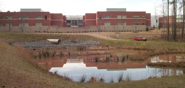
Example of Extended Detention Basin